はじめに
Apple M1 (Mac mini) の PCIe 関連の更新ということで、今年(2021年)3月13日にブログを書きました。
この中のPCIe 部分の図は、下記のようになっています。
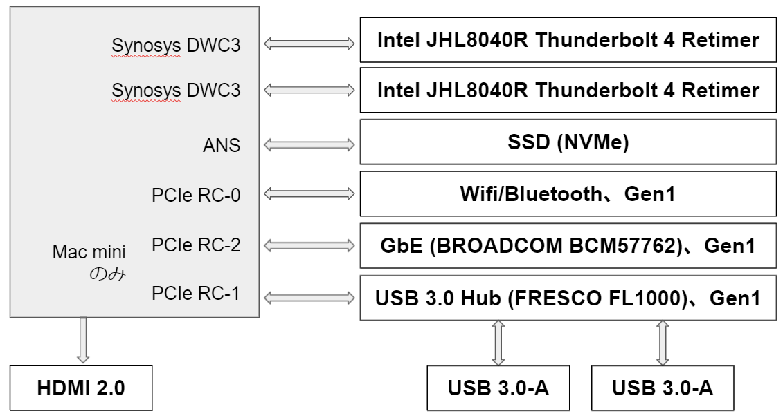
PCIe Gen4 が 3 ポート出ていて、port 0 には、Wifi/Bluetooth、port 1 には GbE、port 2 には USB 3.0 Hub が接続していました
Apple M1 Pro/M1 Max 搭載の Macbook Pro はどうなっている?
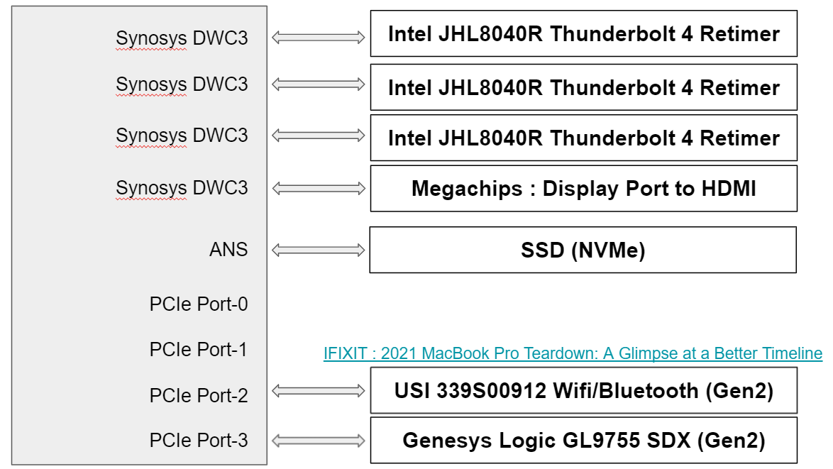
結論から言うと、下図のようになっています。PCIe Gen4 が 4ポートあります。port 2 には Wifi/Bluttooth、port 3 に SDX Controller が接続しているのかな?と思っています。
Asahi Linux の dts を見てみる
M1/M1 Pro/M1 Max搭載のマシンでLinuxを動かすという Asahi Linux の ソースコード(github)のdtsから各デバイスの構成を確認してみました。
master branch ではなく、t6000/bringup-work branch にあります。
t6001.dtsi の PCIe 部分だけを以下に抜き出しました。port00 から port03 までの4ポートあります。port00とport01のmax-link-speedは、"2" (Gen3) ですが、port02とport03のmax-link-speedは、"1" (Gen2) です。Gen2になっているところに、Gen2対応(PCIe 2.1)の Wifi/Bluetooh と SDX Controller が接続しているのだと思います。
     pcie0: pcie@590000000 {
            compatible = "apple,t8103-pcie", "apple,pcie";
            device_type = "pci";

            reg = <0x5 0x90000000 0x0 0x1000000>,
                  <0x5 0x80000000 0x0 0x100000>,
                  <0x5 0x81000000 0x0 0x4000>,
                  <0x5 0x82000000 0x0 0x4000>,
                  <0x5 0x83000000 0x0 0x4000>,
                  <0x5 0x84000000 0x0 0x4000>;
            reg-names = "config", "rc", "port0", "port1", "port2", "port3";

            interrupt-parent = <&aic>;
            interrupts = <AIC_IRQ 0 1270 IRQ_TYPE_LEVEL_HIGH>,
                     <AIC_IRQ 0 1273 IRQ_TYPE_LEVEL_HIGH>,
                     <AIC_IRQ 0 1276 IRQ_TYPE_LEVEL_HIGH>,
                     <AIC_IRQ 0 1279 IRQ_TYPE_LEVEL_HIGH>;

            msi-controller;
            msi-parent = <&pcie0>;
            msi-ranges = <&aic AIC_IRQ 0 1581 IRQ_TYPE_EDGE_RISING 32>;


            iommu-map = <0x100 &pcie0_dart_0 1 1>,
                    <0x200 &pcie0_dart_1 1 1>,
                    <0x300 &pcie0_dart_2 1 1>,
                    <0x400 &pcie0_dart_3 1 1>;
            iommu-map-mask = <0xff00>;

            bus-range = <0 4>;
            #address-cells = <3>;
            #size-cells = <2>;
            ranges = <0x43000000 0x5 0xa0000000 0x5 0xa0000000 0x0 0x20000000>,
                 <0x02000000 0x0 0xc0000000 0x5 0xc0000000 0x0 0x40000000>;

            power-domains = <&ps_apcie_gp_sys>;
            pinctrl-0 = <&pcie_pins>;
            pinctrl-names = "default";

            port00: pci@0,0 {
                device_type = "pci";
                reg = <0x0 0x0 0x0 0x0 0x0>;
                reset-gpios = <&pinctrl_ap 4 0>;
                max-link-speed = <2>;

                #address-cells = <3>;
                #size-cells = <2>;
                ranges;

                interrupt-controller;
                #interrupt-cells = <1>;

                interrupt-map-mask = <0 0 0 7>;
                interrupt-map = <0 0 0 1 &port00 0 0 0 0>,
                        <0 0 0 2 &port00 0 0 0 1>,
                        <0 0 0 3 &port00 0 0 0 2>,
                        <0 0 0 4 &port00 0 0 0 3>;
            };

            port01: pci@1,0 {
                device_type = "pci";
                reg = <0x800 0x0 0x0 0x0 0x0>;
                reset-gpios = <&pinctrl_ap 5 0>;
                max-link-speed = <2>;

                #address-cells = <3>;
                #size-cells = <2>;
                ranges;

                interrupt-controller;
                #interrupt-cells = <1>;

                interrupt-map-mask = <0 0 0 7>;
                interrupt-map = <0 0 0 1 &port01 0 0 0 0>,
                        <0 0 0 2 &port01 0 0 0 1>,
                        <0 0 0 3 &port01 0 0 0 2>,
                        <0 0 0 4 &port01 0 0 0 3>;
            };

            port02: pci@2,0 {
                device_type = "pci";
                reg = <0x1000 0x0 0x0 0x0 0x0>;
                reset-gpios = <&pinctrl_ap 6 0>;
                max-link-speed = <1>;

                #address-cells = <3>;
                #size-cells = <2>;
                ranges;

                interrupt-controller;
                #interrupt-cells = <1>;

                interrupt-map-mask = <0 0 0 7>;
                interrupt-map = <0 0 0 1 &port02 0 0 0 0>,
                        <0 0 0 2 &port02 0 0 0 1>,
                        <0 0 0 3 &port02 0 0 0 2>,
                        <0 0 0 4 &port02 0 0 0 3>;
            };

            port03: pci@3,0 {
                device_type = "pci";
                reg = <0x1800 0x0 0x0 0x0 0x0>;
                reset-gpios = <&pinctrl_ap 7 0>;
                max-link-speed = <1>;

                #address-cells = <3>;
                #size-cells = <2>;
                ranges;

                interrupt-controller;
                #interrupt-cells = <1>;

                interrupt-map-mask = <0 0 0 7>;
                interrupt-map = <0 0 0 1 &port03 0 0 0 0>,
                        <0 0 0 2 &port03 0 0 0 1>,
                        <0 0 0 3 &port03 0 0 0 2>,
                        <0 0 0 4 &port03 0 0 0 3>;
            };
        };
実機で確認する
IFIXITの 2021 MacBook Pro Teardown: A Glimpse at a Better Timeline にて、14インチと16インチのMacbook Proが分解されています。
14インチの基板には、
が搭載されていました。両方とも、PCIe Gen2 (PCIe 2.1) 対応のデバイスのようです。
おわりに
今回、M1 Pro/M1 Max搭載のMacbook Pro 14インチ/16インチの PCIe 周りについて整理しました。