@Vengineerの戯言 : Twitter
SystemVerilogの世界へようこそ、すべては、SystemC v0.9公開から始まった
はじめに
Xilinx QEMU + SystemC (PCIe EP) の内容を探っていく(その1) で説明した、refdesign-sim.cc
のブロック図は下記のようになっています。

QEMUとの通信は、remoteport_tlm_pci_ep が行っています。この remoteport_tlm_pcie_ep に、xilinx_xdma が接続していて、その先に、iconnect (xdma_ic)があって、tlm=>axi bridge を経由して、pcie_bridge_wrapper が接続しています。この pcie_bridige_wrapper は、AXIベースのブリッジRTLモデルです。pcie_bridge_wrapper から axi=>tlm bridge を経由して、iconnect (dut_ic) に繋がり、その iconnect に target の memory と xilinx_cdma が繋がっています。
以降、
について、説明します。
remoteport_tlm_pci_ep
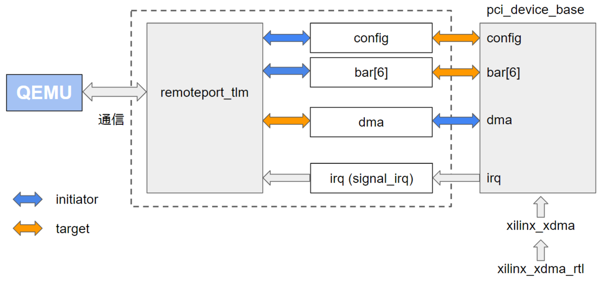
下図は、remoteport_tlm_pci_ep のブロック図です。

XilinxのQEMU + SystemC + Verilog HDL (Verilator) のデモの内容を探っていく(その5)で説明しました remoteport_tlm を使っています。QEMU とは、remoteport_tlm と通信しています。remoteport_tlm からは rst 以外に、4つのポート
- config
- bar[6]
- dma
- irq
が出ています。config と bar[6] は initiator port、dma は target port、irq は bool 型の入力信号です。config と bar[6] は ポインタ (}*)で、dma と irq は リファレンス(&) になっています。
irq のところのコメントにあるように、PCI の MSI/MSI-X はサポートしていません。Legacy な 割り込みのみサポートしています。
```
sc_in
// TLM Socket to serve PCIe Config Space acceses.
tlm_utils::simple_initiator_socket
// BARs (IO or MMIO).
tlm_utils::simple_initiator_socket
tlm_utils::simple_target_socket
// Interrupts.
// For legacy interrupts, this will be a vector of size 1.
// When using MSI/MSI-X, you can either send transactions over the
// dma socket or create a larger irq vector and let the remote-port peer
// convert these signals into MSI/MSI-X messages.
sc_vector
```
上記の図の右側にある pcie_device_base の config, bar[6], dma, irq が remoteport_tlm の config, bar[6], dma, irq と接続することになります。pcie_device_base は、ここ にあります。pci_device_base の config と bar は、target port の実体、dma は initiator port の実体、irq は bool 型の出力信号になっています。bar は sc_vector になっています。bar の数は各デバイスによって変わってくるので、sc_vector にしているようです。
```
// Config Address-Space
tlm_utils::simple_target_socket
// Up to 6 BAR ports.
sc_vector
// A DMA port for end-point access into the host.
tlm_utils::simple_initiator_socket
// Interrupts. Normally this vector will be of size 1.
// Depending on where device connects there may be infrastructure
// to handle multiple interrupts (mapping these signals into MSI).
//
// If not, the DMA port can be used to send MSI/MSI-X interrupts.
sc_vector
```
xilinx_xdma/xilinx_xdma_rtl
全体の図では、pcie_device_base ではなく、xilinx_xdma と remoteport_tlm_pci_ep が接続しています。xilinx_xdma は pcie_device_base を継承したものです。
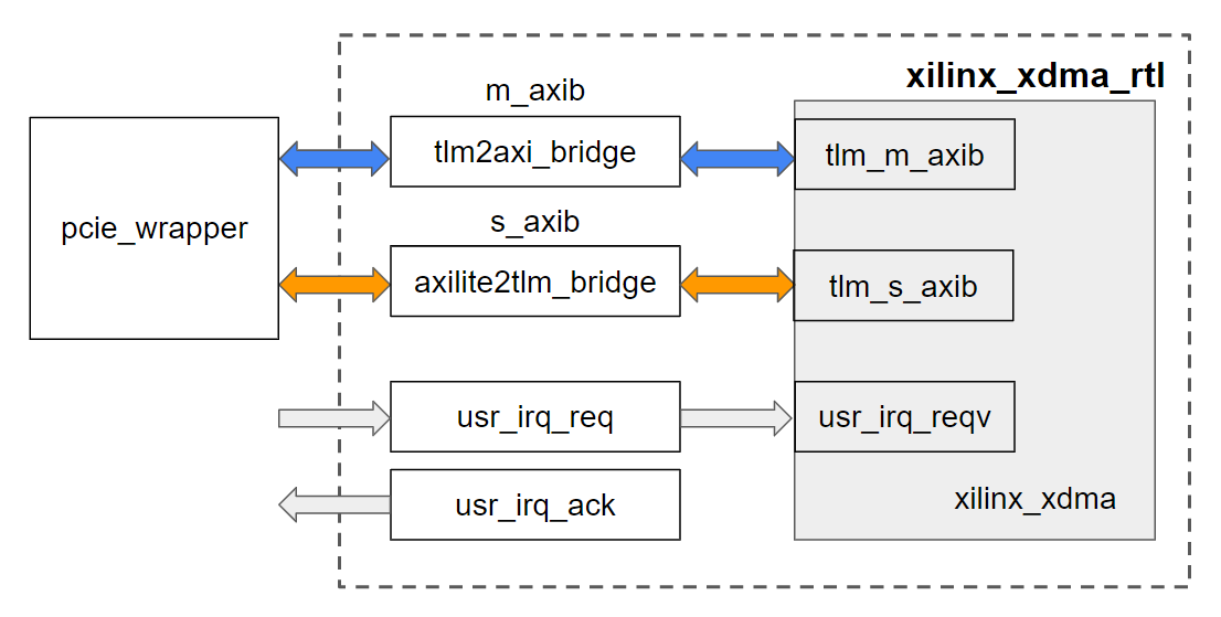
下図に xilinx_xdma のブロック図を示します。xilinx_xdma は、pcie_device_base を継承したものです。

tlm_m_axib という initiator port と tlm_s_axib という target port、そして、usr_irq_reqv という sc_vector な bool 型の入力信号が追加されています。
```
// South-bound towards the EP User-logic.
// These are the AXI4 Memory Mapped Master/Slave Bypass ports.
tlm_utils::simple_initiator_socket
tlm_utils::simple_target_socket
xilinx_xdma_rtl は下記のようなブロック図になっています。xilinx_xdma の tlm_m_axib ポートから tlm2axi_bridge を経由して、pcie_wrapper に接続しています。また、pcie_wrapper から axilite2tlm_bridge を経由して、tlm_s_axib ポートに接続しています。usr_irq_reqv は外部からの 割り込み信号である usr_irq_req が接続されています。usr_irq_req に対して、usr_irq_ack も追加されています。

pcie_bridge_wrapper
pcie_bridge_wrapper は、refdesign-sim.cc の中で定義されています。下記のように pcie_bridge_wrapper は、Verilog HDL の pcie_ep.v の Wrapper file です。Vpcie_ep の最初の V が Verilog HDL (Verilator)のモデルを意味します。
```
SC_MODULE(pcie_bridge_wrapper)
{
public:
Vpcie_ep ep_bridge;
sc_in
sc_in
sc_in
```
pcie_ep.v の説明は、ここ にあります。
サポートしている機能は、こんな感じです。
- DUT Protocol support - AXI4 and AXI4-Lite
- DUT AXI Data widths - 32, 64,128-bit
- Slave AXI interface to configure bridge registers - 32-bit AXI4-Lite slave
- Outstanding Transactions - As per AXI Master, Slave Bridge
- Mode of operation : Mode_0, Mode_1
- Interrupt support : Legacy PCIe only
Initiator 、Target それぞれ、6ポートまでサポートしています。